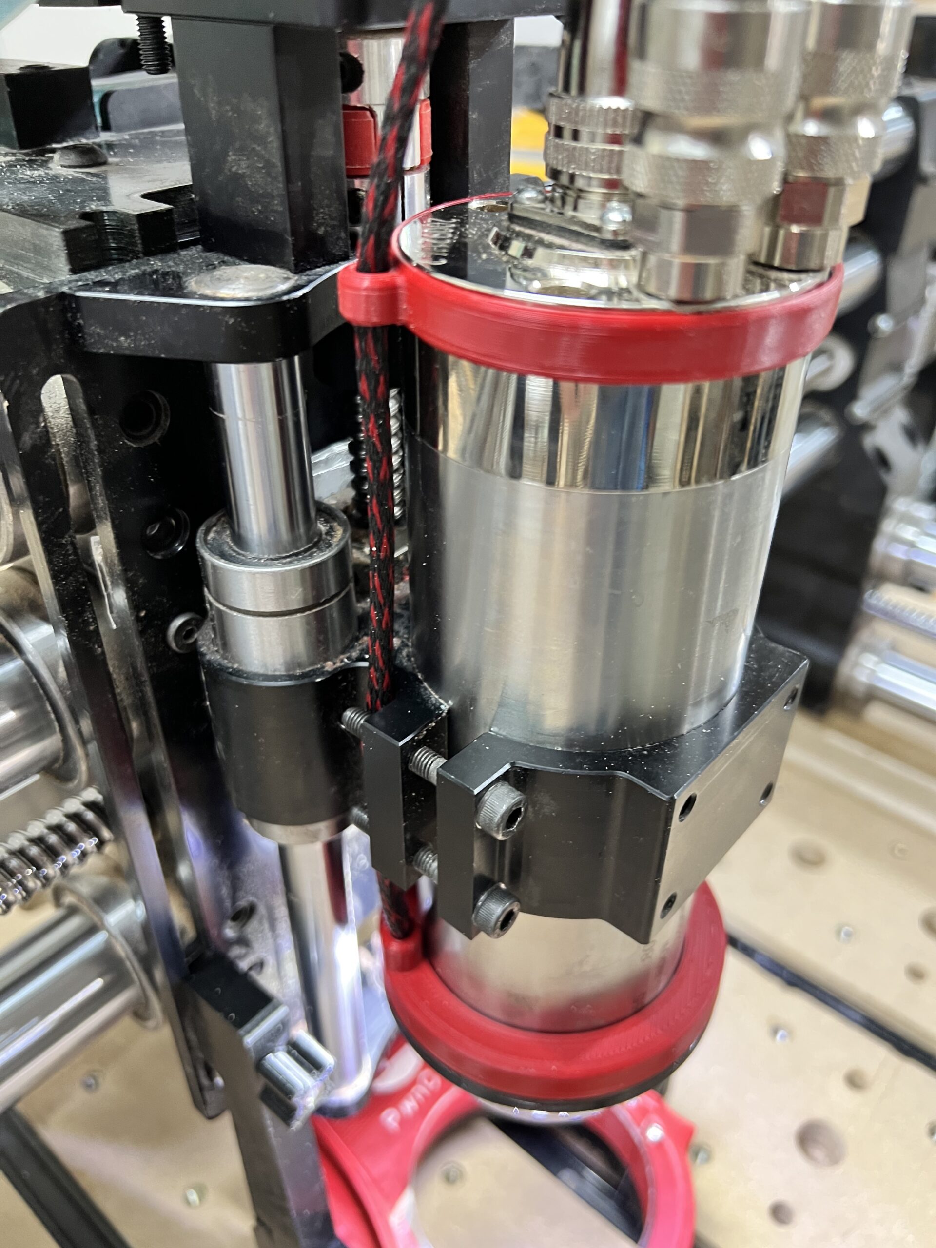
Materials ReQUIRED:
- 3D Printed Parts (STL files available here)
- LED Ring Light (for 65mm or for 80mm)
- 24 AWG Silicon Wire
- Neoprene Strip
- Heat Shrink Tubing
- 2mm Zip Ties
- Neoprene Strip
- 12V DC 1A Power Supply (optional)
Please Note: Any Amazon affiliate links above help pay our hosting fees.
TOOLS REQUIRED:
- Wire Snips
- Wire Stripper
- Soldering Iron or Soldering Station
- Heat Gun or Lighter
Estimated Time To Complete:
20 – 30 Minutes
STeP 1
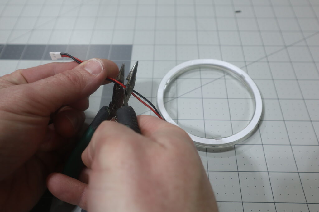
Cut off the connector about half way between the connector and the light ring (err on cutting closer to the connector).
STeP 2
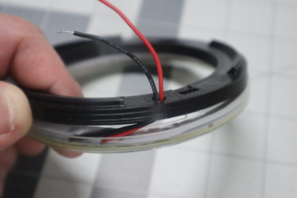
Run the wire through the single hole and line up the 3 holes in the base with the 3 tabs on the LED ring. Make sure that both wires are routed over the LED Ring so that they do not get pinched between the base and the ring when the two are put together.
STeP 3
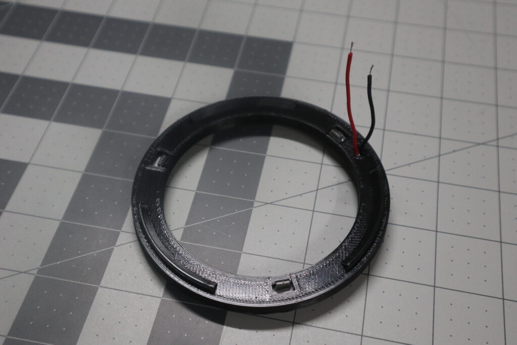
Attach the base to the ring ensuring that each of the 3 tabs snap into place.
Note!
If you have trouble getting the ring to snap in easly, double check to ensure that any imperfections from the printing process have been removed. A small bit of excess filament can prevent the ring from seating properly. This is particularly true with the 65mm version.
STeP 4
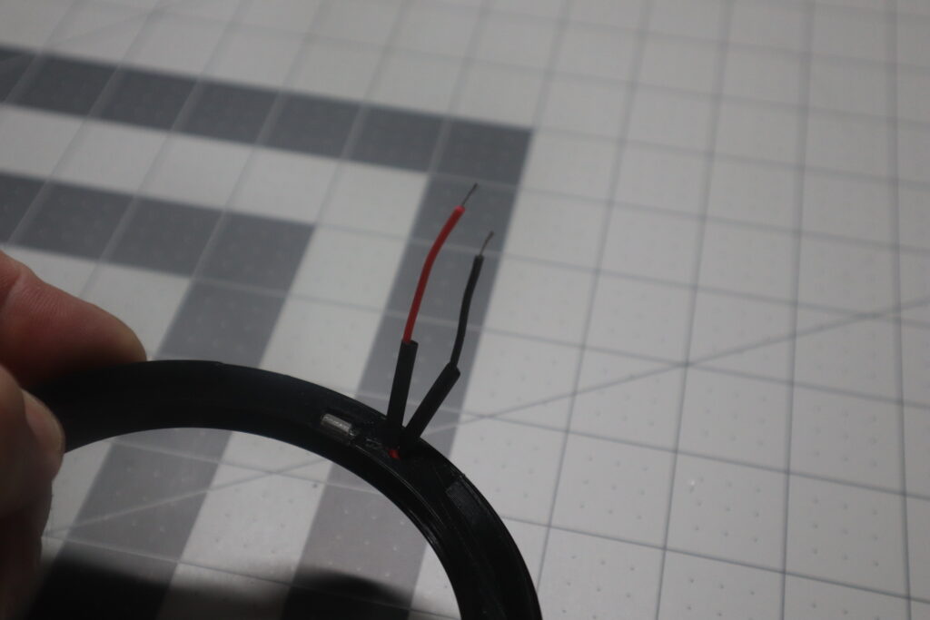
Cut one of the 1/8″ heat shrink tubes in half and put one half on each of the wires. Let both pieces rest against the base for now. Leave both tubes unshrunk.
STeP 5
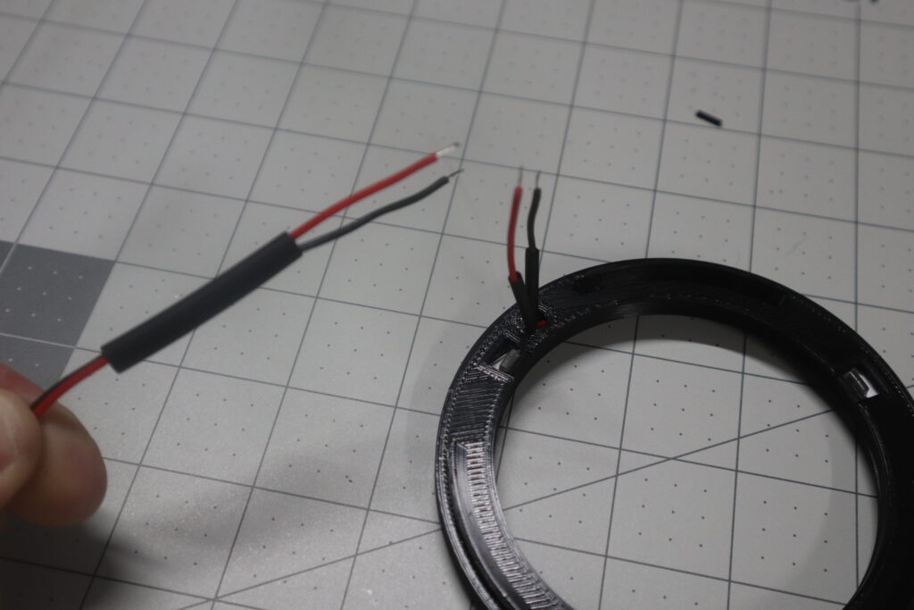
Take the piece of 1/4″ heat shrink tube and run it over both the wires on the main wire run. Slide it out of the way for now and leave it unshrunk.
STeP 6
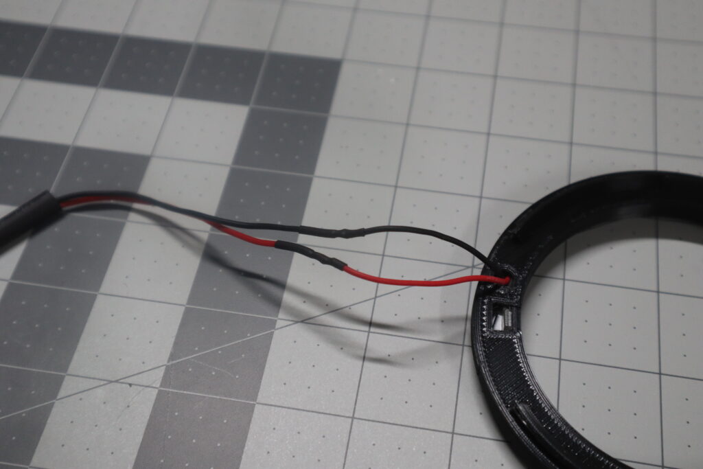
Carefully solder both wires together taking care to make a good clean connection. Using too much solder may prevent the heat shrink tubing from sliding on easily. Slide both small heat shrink tubes over the soldered connections taking care to cover both completely and apply heat to shrink them into place completing the splice.
STeP 7
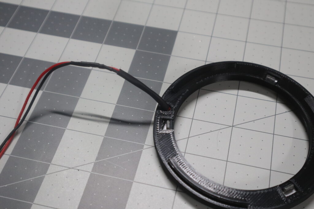
Now that the wires are spliced together, slide the 1/4″ heat shrink tube all the way down to the hole where the wires come through the base and apply heat to shrink it in place there at the very bottom against the base. This serves to help with strain relief and does not need to cover the splice.
STeP 8
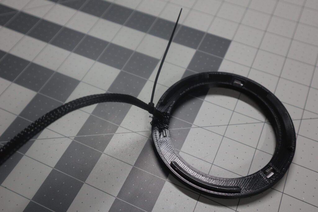
Work the nylon sheath all the way down so that it’s just touching the base and securely apply one of the 2mm zip ties about 3/4″ up from the base. This will hold the sheath in place and help provide strain relief. Once the zip tie is secure clip off as much of the excess as possible.
STeP 9
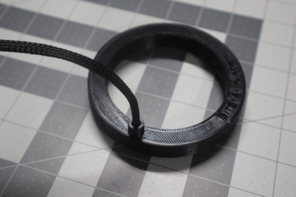
Starting from the other end of the sheath, work the cover down and snap in in place over the base. A small bit of tape wrapped around the end of the sheath makes it easy to work through the cover if needed. Note that the cover can be removed by simply twisting it.
STeP 10
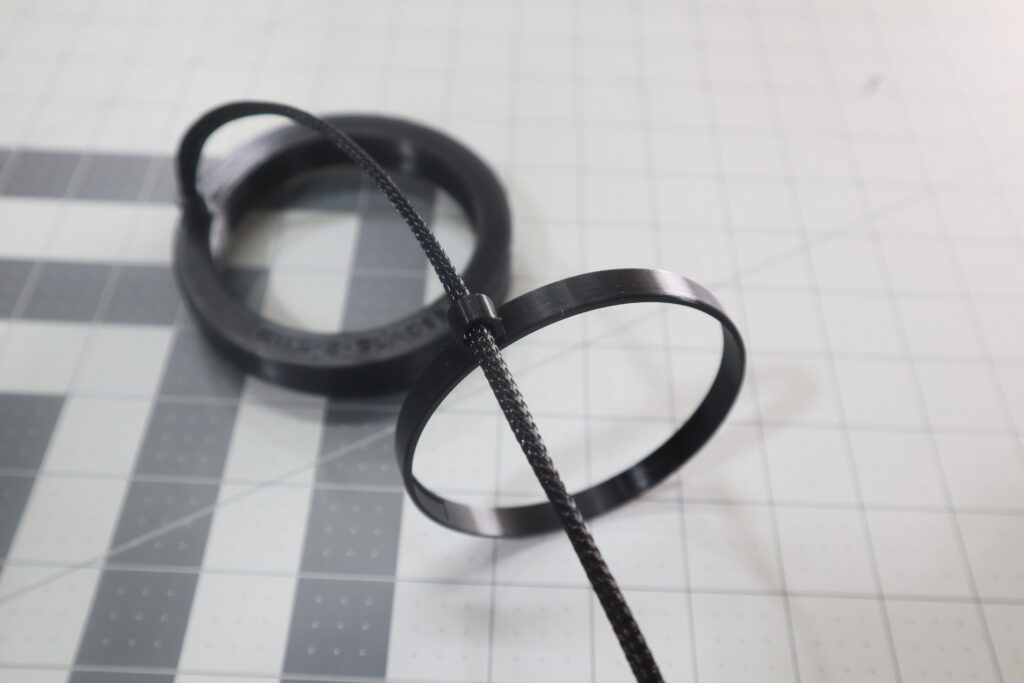
If you are going to use the clip, now is the time when you’d want to put it on. The wire should be fed through the side of the clip with the large hole. The idea being that a 2mm zip tie could hide in their if needed.
STeP 11
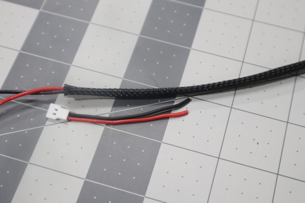
Take the end with the connector that you cut off of the LED ring and lay it next to the other end of the nylon sheathing. Take note of how far back you will need to cut the wires so that when the connector is spliced on, it will extend just past the end of the sheathing. Make sure to fully extend the sheathing before taking the measurement.
STeP 12
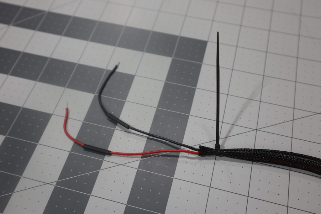
Trim the wires to the determined length and splice the connector on using the same method from steps 4 & 6. You can use another small zip tie to temporarily hold the sheath back while you solder the ends together.
STeP 13
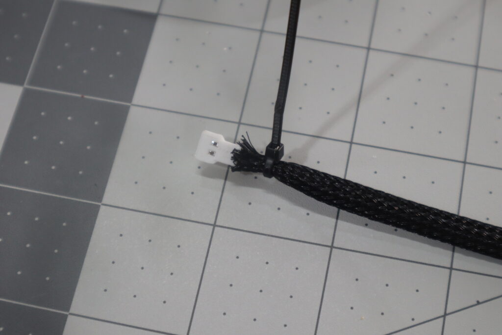
Pull the nylon sheath back up to the connector and use another 2mm zip tie to hold it in place. After tightening down the zip tie, clip off as much of its excess tail as possible.
STeP 14
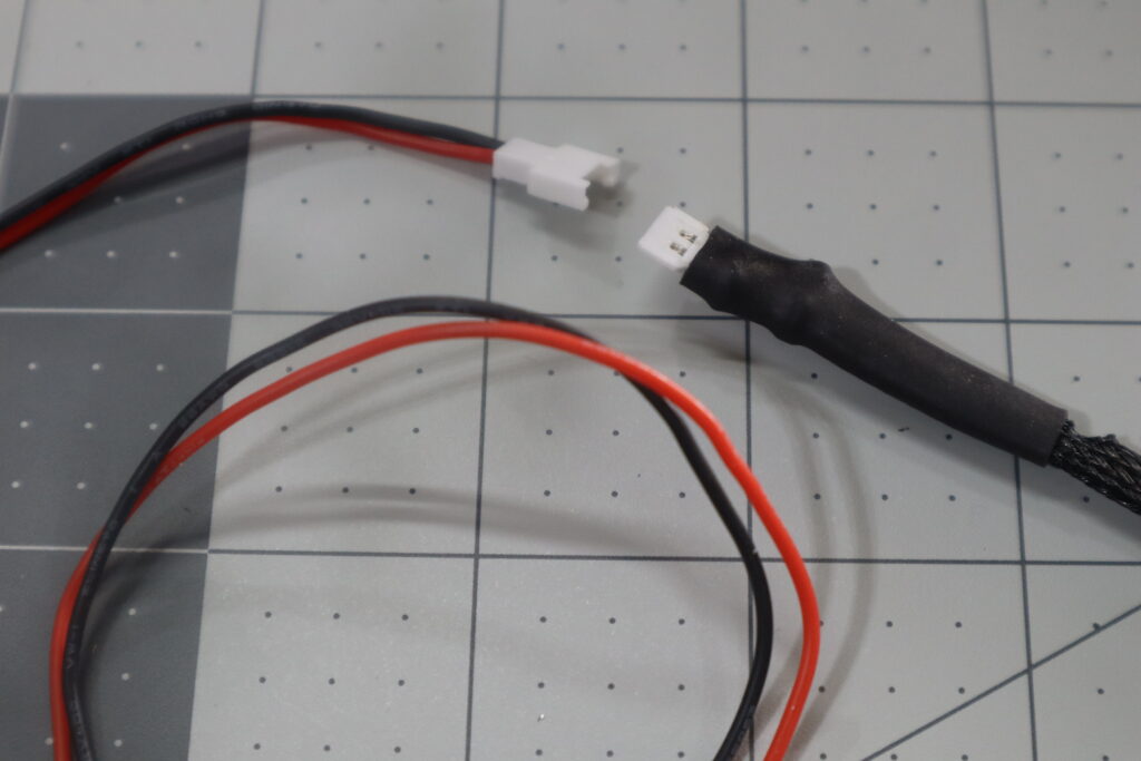
Place a piece of 1/2″ heat shrink tube over the end of the connection so that it covers the end of the sheath, the zip tie and the very back of the connector (but not the pins) and apply heat. Now you will be able to connect into the other piece that came with the light that has the current limiter (little black box that came with the LED ring).
STeP 15
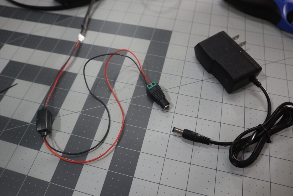
Connect the other end of the original LED ring wiring to your 12/24V DC Adaptor. Note that the LED ring draws around 300 mA at 12V or 150 mA at 24V. Your power adaptor should be sized accordingly. If you’re using a DC Adapter provided by Bits 2 Blades, it will include a solderless female terminal adapter. Connect the red wire to the + and the black wire to – on the terminal.
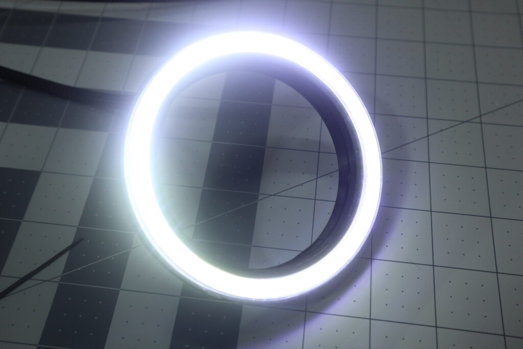
STep 16 – You’re Almost THERE!
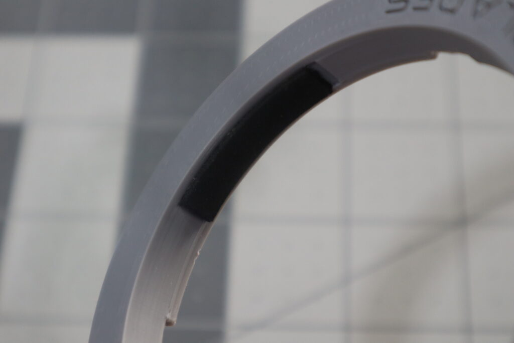
Carefully apply the neoprene strips to the inside of the cover (and clip if you’re using it). Both parts have small recessed areas to help prevent the neoprene from wanting to roll out. When working with the neoprene, avoid touching the adhesive and try to get it all in the recessed areas. Make sure that it’s firmly attached before putting it on your spindle.
Gently slide the light onto the bottom of the spindle taking care not to roll the neoprene out.
Verify that the body of the light has enough clearance between itself and other parts of the CNC.
That’s it! You’re done!
Hopefully this article provided you with all the information needed to easily assemble the “DIY” version of our Universal CNC Spindle Light. If you found something unclear, or you have a suggestion for how we could improve the process, please leave us a comment below!
